Digital Systems Lab - Winter 2025
::: {#title-block-header}
Digital Systems Lab - Winter 2025 {#digital-systems-lab---winter-2025 .title}
Prof. Guillaume Hoffmann :::
- [1]{.toc-section-number} Week 1{#toc-week-1}
- [2]{.toc-section-number} Week 2{#toc-week-2}
- [3]{.toc-section-number} Week 3{#toc-week-3}
- [4]{.toc-section-number} Week 4{#toc-week-4}
- [5]{.toc-section-number} Week 5{#toc-week-5}
- [6]{.toc-section-number} Week 6{#toc-week-6}
- [7]{.toc-section-number} Week 7{#toc-week-7}
- [8]{.toc-section-number} Week 8{#toc-week-8}
- [9]{.toc-section-number} Week 9{#toc-week-9}
- [10]{.toc-section-number} Week 10{#toc-week-10}
- [11]{.toc-section-number} Week 11{#toc-week-11}
[1]{.header-section-number} Week 1 {#week-1 number="1"}
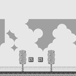
[1.1]{.header-section-number} Introducing the platform {#introducing-the-platform number="1.1"}

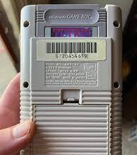
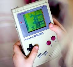
- Nintendo Game Boy: videogame console
- Released in 1989
- 120 million units sold worldwide
- Low cost, low energy consumption
- 8 bits CPU (name: SM83, sometimes called GBz80)
- 160x144 pixels display, 4 shades of green
- Still relevant in 2023 for education, research and fun
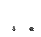
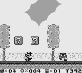
[1.2]{.header-section-number} Game examples {#game-examples number="1.2"}


[1.3]{.header-section-number} The Game Boy CPU {#the-game-boy-cpu number="1.3"}
- a custom CPU made by Sharp (Japan)
- it imitates closely two existing popular CPUs:
- Intel 8080: used in personal computers, the precursor of the x86 family still in use today
- Zilog Z80: used in many personal computers of the 1970s and 1980s, and pocket calculators
[1.4]{.header-section-number} Our plan {#our-plan number="1.4"}
- first weeks: get to know the CPU
- then: get to know the platform
- a computer is not only the CPU itself!
- it is: CPU + memory map + graphic device + buses
- later weeks of semester: get the platform to work to run graphical programs
- we will cover ~60% of the platform
- objectives:
- get experience in assembly programming
- understand the implications of defining a stored program without a compiler
- understand low-level issues of timing, instruction sizes
[1.5]{.header-section-number} Instructions and instructions set {#instructions-and-instructions-set number="1.5"}
- Instructions are used to control a CPU
- Each instruction causes the CPU to perform a very specific task
- Each CPU has its own instruction set, that is a fixed set of instructions that it can understand.
- A program in machine code consists of a sequence of machine instructions and will only work on a specific CPU model
[1.6]{.header-section-number} The CPU {#the-cpu number="1.6"}
                        CPU
                 +--------------+
                 |              |
instructions ->  |   internal   |
                 |    state     |
                 |              |
                 +--------------+
                        CPU
                 +--------------+
                 |   8-bit      |
instructions ->  |  registers   |
                 |              |
                 | a,b,c,d,e,h,l|
                 +--------------+
                        CPU
...              +--------------+
instr1           |   8-bit      |
instr2       ->  |  registers   |
instr3           |              |
...              | a,b,c,d,e,h,l|
                 +--------------+
- What are registers?
- each register == 8 bits
- think of them as C variables char/uint8
- cannot add more registers
ais often called the "accumulator"- What are instructions?
- small commands that tell the CPU to do something
- very simple syntax
[1.7]{.header-section-number} Assembly language (ASM) {#assembly-language-asm number="1.7"}
- ASM == writing programs as a sequence of instructions
- almost no syntax!
- instructions are very different from C statements
- there are infinitely many C statements
- there are finitely many ASM instructions
. . .
. . .
Example:
:::::::: columns :::: {.column style="width:40%;"} In C:
```{.sourceCode a = 20; b = 40; c = 50; d = (a + b) + c;
::::

::: {.column style="width:10%;"}
:::

:::: {.column style="width:40%;"}
In ASM:

```{.sourceCode
ld a,20
ld b,40
ld c,50
add b
add c
ld d,a
:::: ::::::::
[1.8]{.header-section-number} ASM syntax {#asm-syntax number="1.8"}
```{.sourceCode ld a,10 ; decimal notation ld b,20 add b ; a = a + b ld b,a ld a,%00001111 ; binary notation ld c,%11000000 or c ; a = a | c ld c,$F0 ; hexadecimal notation xor c ; a = a ^ c
Format type   Prefix   Accepted characters

---

Hexadecimal   `$`      `0123456789ABCDEF`
Decimal       none     `0123456789`
Binary        `%`      `01`

- A numerical constant is also called an "immediate" in assembly.
- The syntax is line-based, meaning that you do one instruction per
  line.
- Uppercase/lowercase does not matter

## [1.9]{.header-section-number} Today's instructions {#todays-instructions number="1.9"}

We will cover part of the following:

- 8-bit load instructions
- 8-bit arithmetic and logic instructions
- arithmetic shift instructions

Then do a few exercises.

## [1.10]{.header-section-number} 8-bit load instructions {#bit-load-instructions number="1.10"}
ld r,r r=r ld r,n r=n
- r is one of the registers `a,b,c,d,e,h,l`
- n is a 1 byte constant
- examples:
  - `ld a,b`
  - `ld b,a`
  - `ld b,10`
  - `ld b,%00001010` (equivalent to previous one)
  - `ld h,l`

## [1.11]{.header-section-number} increment/decrement instructions {#incrementdecrement-instructions number="1.11"}
inc r r=r+1 dec r r=r-1
- examples:
  - `inc a`
  - `inc b`
  - `inc c`
  - `dec d`
  - `dec e`
  - `dec h`...

## 1.12 8-bit arithmetic instructions with register or constant arguments
add r A=A+r add n A=A+n sub r A=A-r sub n A=A-n
- `a` is always the first argument of these instructions
- `a` is also called the "accumulator"
- in some documentation, they are written with `a` as first argument:
  - `add a,b`
  - `sub a,c`
- the Game Boy CPU has no multiply and divide instructions

## [1.13]{.header-section-number} 8-bit logic instructions with register or constant arguments {#bit-logic-instructions-with-register-or-constant-arguments number="1.13"}
and r A=A & r and n A=A & n xor r A=A ^ r xor n A=A ^ n or r A=A | r or n A=A | n cpl A = A xor FF (invert all bits of A)
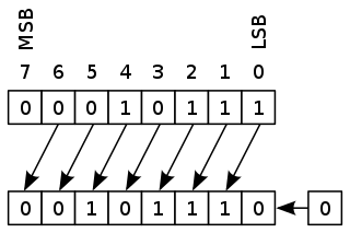
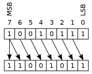
## [1.14]{.header-section-number} Arithmetic Shift instructions {#arithmetic-shift-instructions number="1.14"}
sla r shift left arithmetic (b0=0) sra r shift right arithmetic (b7=b7)
`sla:`
`sra:`
## [1.15]{.header-section-number} Exercise 1 {#exercise-1 number="1.15"}
What are the final values of all registers of this snippet?
```{.sourceCode
LD A,0
LD B,0
INC A
INC B
ADD B
LD C,A
LD D,10
ADD D
You can write the answer in the most convenient way (decimal, binary or hexa).
When writing answer in decimal, use the most convenient way between unsigned and signed.
E.g., -128 and 128 are considered the same number; -1 and 255
are considered the same number.
[1.16]{.header-section-number} Exercise 2 {#exercise-2 number="1.16"}
What are the final values of all registers of this snippet?
```{.sourceCode LD A,100 LD B,50 LD C,20 SUB B SUB C SUB C DEC B INC C
## [1.17]{.header-section-number} Exercise 3 {#exercise-3 number="1.17"}

```{.sourceCode
LD A,0
LD B,255
DEC A
INC B
A,B?
```{.sourceCode LD A,100 LD B,100 ADD B ADD B
A,B?

```{.sourceCode
LD A,100
LD B,100
SUB B
SUB B
A,B?
[1.18]{.header-section-number} Exercise 4 {#exercise-4 number="1.18"}
```{.sourceCode LD A,%00000000 LD B,%10101010 OR B
A, B?

```{.sourceCode
LD A,%00001111
LD B,%10101010
OR B
A, B?
```{.sourceCode LD A,%00001111 LD B,%10101010 AND B
A,B?

## [1.19]{.header-section-number} Exercise 5 {#exercise-5 number="1.19"}

```{.sourceCode
LD A,$0F
LD B,$AA
XOR B
A,B?
```{.sourceCode LD A,\(0F LD B,\)BB CPL LD B,A
A,B?

# [2]{.header-section-number} Week 2 {#week-2 number="2"}

## [2.1]{.header-section-number} Topics {#topics number="2.1"}

- stored programs
- labels and jump instructions
- flags
- conditional jumps
- C-like control flow in assembly: if, if-else, do-while, while

## [2.2]{.header-section-number} Addressable Memory {#addressable-memory number="2.2"}

- The addressable memory is storage than can be accessed (read and
  write) by means of an address.
- Think of the addressable memory as a big array, and you can do:
  - `register = memory[address]` to read
  - `memory[address] = register` to write
- `address` is a value from `$0000` to `$FFFF`
- `register` is a value from `$00` to `$FF`
- In other words, between the CPU and the memory, there is an address
  bus of 16 bits and a data bus of 8 bits.

## [2.3]{.header-section-number} Stored programs {#stored-programs number="2.3"}

- Not only data is stored in memory, programs too.
- Each instruction of a stored program has an address, eg:

```{.sourceCode
$0000 | XOR A
$0001 | LD B,A
$0002 | LD C,A
$0003 | INC C
$0004 | INC C
$0005 | ADD A,C
. . .
- Instructions are normally executed in increasing order of memory address.
- Conditions and loops are implemented with special instructions called "jumps".
[2.4]{.header-section-number} jp and labels {#jp-and-labels number="2.4"}
Mnemonic     Description
------------ -------------------------
jp nn        jump to memory address nn
An infinite loop:
```{.sourceCode mylabel: instruction1 instruction2 instruction3 jp mylabel
- The value of `mylabel:` is the memory address of the next instruction.
- We do not need to know the actual value because the assembler takes
  care of calculating the memory address of all labels in a program.
- A label is not an instruction. Machine code does not contain labels
  (unless it includes debug information).

## [2.5]{.header-section-number} Introducing flags {#introducing-flags number="2.5"}
- zero flag: a single bit
  - meaning: "last instruction result is zero"
- carry flag: a single bit
  - meaning: "last instruction produced a carry bit"

Vocabulary:

- to set a bit: set its value to 1
- to reset a bit: set its value to 0

## [2.6]{.header-section-number} Conditional jumps {#conditional-jumps number="2.6"}
jp f,nn conditional jump if nz,z,nc,c
Conditions (f):

- nz: jump if not zero
- z: jump if zero
- nc: jump if not carry
- c: jump if carry

## [2.7]{.header-section-number} How instructions affect zero and carry flags {#how-instructions-affect-zero-and-carry-flags number="2.7"}

- load instructions do not affect flags
- inc/dec
  - zero flag set iff result is zero
  - does not affect carry flag
- and/or/xor:
  - zero flag set iff result is zero
  - always reset carry flag
- add/sub instructions affect zero and carry flags
  - zero flag set iff result is zero
  - carry flag set iff operation creates a carry/borrow bit

## [2.8]{.header-section-number} A loop example {#a-loop-example number="2.8"}

```{.sourceCode
  ld b,10
loop:
  ...
  [instructions that do not affect b]
  ...
  dec b
  jp nz,loop
[2.9]{.header-section-number} Comparing values {#comparing-values number="2.9"}
Mnemonic     Description
------------ ------------------
cp r         compare A-r
cp n         compare A-n
- cp performs a
subbut does not save the result, only zero and carry flags are affected - to jump to
labelifa == b:cp bthenjp z, label - to jump to
labelifa >= b(aandbconsidered unsigned):cp bthenjp nc, label - to jump to
labelifa < b(aandbconsidered unsigned):cp bthenjp c, label
[2.10]{.header-section-number} Another loop example {#another-loop-example number="2.10"}
```{.sourceCode ld b,0 loop: ... [instructions that do not affect b] ... inc b ld a,b cp 10 jp nz,loop
## [2.11]{.header-section-number} Program Counter {#program-counter number="2.11"}

How does the CPU store the address of the current instruction?

It has an extra register called `PC` "program counter":
This explains the following description of `jp`:
jp nn jump to nn, PC=nn
There are no instructions that let you use `pc` as a normal register (to
store data, do arithmetic).

## [2.12]{.header-section-number} Exercise 1 {#exercise-1-1 number="2.12"}

Convert the following high-level code to assembly.

```{.sourceCode
if (d == e)
  [CODE1]
[CODE2]
```{.sourceCode if (d == e) [CODE1] else [CODE2] [CODE3]
## [2.13]{.header-section-number} Exercise 2 {#exercise-2-1 number="2.13"}

Convert the following high-level code to assembly.

```{.sourceCode
c=0;
do {
  [CODE1]
} while (++c != 10);
[CODE2]
[2.14]{.header-section-number} Exercise 3 {#exercise-3-1 number="2.14"}
Convert the following high-level code to assembly. Explain which
registers correspond to variables pow and x. You are allowed to
destroy other registers.
```{.sourceCode int pow = 1; int x = 0;
while (pow != 64){ pow = pow * 2; x = x + 1; }
## [2.15]{.header-section-number} Exercise 4 {#exercise-4-1 number="2.15"}

Same exercise.

```{.sourceCode
int sum = 0, i;

for (i = 0; i != 10; i = i + 1) {
  sum = sum + i ;
}
[3]{.header-section-number} Week 3 {#week-3 number="3"}
[3.1]{.header-section-number} Topics {#topics-1 number="3.1"}
- 16-bit registers
- 16-bit load and arithmetic instructions
- memory addressing
[3.2]{.header-section-number} 16-bit registers {#bit-registers number="3.2"}
- 3 pairs of registers from existing registers
BC,DE,HL- treated as a single 16-bit register by a few instructions
- any instruction that modifies
BCmay modifyBorC, even both
[3.3]{.header-section-number} 16-bit Load instructions {#bit-load-instructions-1 number="3.3"}
Mnemonic     Description
------------ -----------------------------------------
ld rr,nn     rr=nn
nnis a constantrrcan only beBC,DEorHL- To load from other 16-bit registers, use 2
LD8-bit instructions: ld h,bld l,c
[3.4]{.header-section-number} 16-bit arithmetic instructions {#bit-arithmetic-instructions number="3.4"}
Mnemonic      Description
------------- --------------------------------------------
inc rr        rr = rr+1
dec rr        rr = rr-1
add HL,rr     HL = HL+rr
rrcan only beBC,DEorHL- 16-bit inc/dec do not update any flag
- 16-bit add updates the carry flag, but not the zero flag
- there are no 16-bit logic instructions
[3.5]{.header-section-number} Exercise 1 {#exercise-1-2 number="3.5"}
Write a code snippet in which a loop is controlled by BC and repeated
1000 times.
[3.6]{.header-section-number} Memory addressing {#memory-addressing number="3.6"}
- let us see instructions to load and store data from/to memory to register CPUs
- this means we can use the memory to read and store data
- notation:
(nn)or[nn]: the value stored at memory addressnn- similar to the
*operator of the C language - same for
(rr)or[rr]whenrris a 16-bit register
[3.7]{.header-section-number} Load from/to memory instructions with the HL register {#load-fromto-memory-instructions-with-the-hl-register number="3.7"}
Mnemonic        Description
--------------- -------------------------------------
ld r,(HL)       r=(HL)
ld (HL),r       (HL)=r
ld (HL),n       (HL)=n
- memory is written/read one byte at a time
HLas a memory address can be used in combination with any 8-bit register
[3.8]{.header-section-number} More load from/to memory instructions {#more-load-fromto-memory-instructions number="3.8"}
Mnemonic        Description
--------------- -------------------------------------
ld A,(BC)       A=(BC)
ld A,(DE)       A=(DE)
ld (BC),A       (BC)=A
ld (DE),A       (DE)=A
ld A,(nn)       A=(nn)
ld (nn),A       (nn)=A
Acan be used in combination with any 16-bit register address or 16-bit constant address- the other combinations are not possible:
ld (nn),nld E,(BC)
[3.9]{.header-section-number} Exercise 2 {#exercise-2-2 number="3.9"}
Write a code snippet that sets B bytes of memory to 0, starting from
address HL. You may assume that B is not equal to 0.
[3.10]{.header-section-number} Exercise 3 {#exercise-3-2 number="3.10"}
Write a code snippet that copies B bytes from address DE to address
HL. You may assume that B is not equal to 0.
[3.11]{.header-section-number} Exercise 4 {#exercise-4-2 number="3.11"}
Write a code snippet that copies BC bytes from address DE to address
HL. The code snippet should do nothing if it detects that BC is
equal to 0.
[3.12]{.header-section-number} Exercise 5 {#exercise-5-1 number="3.12"}
Write a code snippet sumArray: that expects a memory address in DE,
a non-null integer value in B, and performs the sum of the first B
bytes in memory starting from address DE, and saves the sum in
register HL.
[4]{.header-section-number} Week 4 {#week-4 number="4"}
[4.1]{.header-section-number} Contents {#contents number="4.1"}
- the
spregister - stack instructions
- functions:
callandretinstructions - preserving values
(hl)as operand
[4.2]{.header-section-number} The sp register {#the-sp-register number="4.2"}
- another 16-bit register, dedicated to memory addressing
spstands for "stack pointer"- it is used as a way to store and read values in memory at a particular location
- when the Gameboy boots up, initialized at
$FFFE
[4.3]{.header-section-number} The stack, as an Abstract Datatype {#the-stack-as-an-abstract-datatype number="4.3"}
The stack is implemented with a pointer to memory and two operations:
- push(x): stores value x in memory, decrease pointer.
- pop(): returns value from pointer, increase pointer.
These operations mean that we can only get the latest value pushed on the stack. A stack is a first-in-last-out data structure (or last-in-first-out).
[4.4]{.header-section-number} Stack instructions {#stack-instructions number="4.4"}
Mnemonic     Description
------------ -----------------------------------------
push rr      SP--, (SP)=MSB(rr), SP--, (SP)=LSB(rr)
pop rr       LSB(rr)=(SP), SP++, MSB(rr)=(SP), SP++
- MSB: most significant byte
- LSB: least significant byte
rrcan only beBC,DE,HL, or AFAFis the pair of registersAand the flag registerF.Fcontains the flags and a few unused bitsFcan only be used inPUSH AFandPOP AF
[4.5]{.header-section-number} Good use of the stack {#good-use-of-the-stack number="4.5"}
- always push before pop
- use as many pop's as push's
- do not access stack memory manually, use push/pop
[4.6]{.header-section-number} Exercise 1 {#exercise-1-3 number="4.6"}
```{.sourceCode ld hl,10 ld bc,20 ld de,30 push hl push bc push de pop hl pop bc pop de
What are the final values of `hl`, `bc`, `de`?

## [4.7]{.header-section-number} Exercise 2 {#exercise-2-3 number="4.7"}

Write a code snippet `concat:` that takes three memory addresses `HL`,
`DE` and `BC` and a non-zero integer `A`. `HL` and `DE` are
zero-terminated strings that must be copied one after another to the
location `BC`. `A` is the maximum size of the `BC` buffer. A final zero
must be written at the end of the `BC` string, only if the size of the
buffer allows it.

## [4.8]{.header-section-number} `call` and `ret` instructions {#call-and-ret-instructions number="4.8"}
call nn equivalent to PUSH PC, PC=nn call f,nn conditional call if nz,z,nc,c ret return: equivalent to POP PC ret f conditional return if nz,z,nc,c
- calling a function means saving the return address of the calling
  environment on the stack
- returning from a function means taking back the return address from
  the stack and jumping back to that address
- like `push` and `pop`, `call` and `ret` are expected to be used
  together
- nested calls work as expected

## [4.9]{.header-section-number} Function example {#function-example number="4.9"}

```{.sourceCode
; input: HL: base address
;         B: index
; output: A: = [HL+B]
; modifies: HL
getArrayIdx:
  ld a,l
  add a,b
  jp nc, getValue
  inc h
getValue:
  ld l,a
  ld a,[hl]
  ret
[4.10]{.header-section-number} Same with HL preservation {#same-with-hl-preservation number="4.10"}
```{.sourceCode ; input: HL: base address ; B: index ; output: A: = [HL+B] getArrayIdx: push hl ld a,l add a,b jp nc, getValue inc h getValue: ld l,a ld a,[hl] pop hl ret
## [4.11]{.header-section-number} Exercise 3 {#exercise-3-3 number="4.11"}
Write a function `sameSum` that expects a memory address in `DE`, a
positive integer value in `B`, and performs the sum of the first `B`
bytes in memory starting from address `DE`, then the sum of the next `B`
bytes in memory; if both sum are equal, it sets `A` to `1` and returns,
otherwise it sets `A` to `0` and returns. The function should preserve
registers `DE` and `HL`.
## [4.12]{.header-section-number} `(hl)` as operand {#hl-as-operand number="4.12"}
`(hl)` can be used as an operand in (almost) all instructions instead of
a register operand.
Hence, these instructions exist:
- `add/sub (hl)`
- `or/and/xor (hl)`
- `cp (hl)`
In these instructions, the value stored at memory address `hl` is taken
as second operand, and the result is stored in `a` as usual (except `cp`
that only updates flags).
- `inc/dec (hl)`
With this one, the value stored at memory address `hl` is updated.
## [4.13]{.header-section-number} Exercise 4 {#exercise-4-3 number="4.13"}
Write a function `duplicates:` that checks if the array stored in memory
at address `HL` and of size `B` contains duplicated values; it should
set `A` to 1 if it does, `A` to 0 if it does not, then it should return.
Hint: use two nested loops, and use `HL` and `DE` as two memory
locations inside of the array. Use both `B` and `C` as loop counters.
If you do not use the `cp (HL)` instruction, you will need to use the
stack.
## [4.14]{.header-section-number} Exercise 5 {#exercise-5-2 number="4.14"}
Assume you have three constants `LT`, `EQ` and `GT` defined in your
program (for instance, they are respectively equal to 0,1 and 2).
Define a function `compare` that uses registers `A` and `B` as inputs,
and `A` as output. It should return `A` equal to `LT` if `A<B`, `A`
equal to `EQ` if `A==B`, and `A` equal to `GT` otherwise, considering
`A` and `B` as unsigned.
The function must not involve conditions on the carry flag and it may
destroy the values of registers `A`, `B` and `C` only.
# [5]{.header-section-number} Week 5 {#week-5 number="5"}
## [5.1]{.header-section-number} Contents {#contents-1 number="5.1"}
- Toolchain: from `.asm` to `.gb` file
- The Game Boy memory map
- Instructions encoding
- Sections
- Absolute addresses
- Relative addresses
- Labels in `RGBASM`
## [5.2]{.header-section-number} Tools for programming {#tools-for-programming number="5.2"}
- RGBDS: [https://rgbds.gbdev.io](https://rgbds.gbdev.io)
- a collection of free and open-source software
- `rgbasm`: assembler; from an input `.asm` file, generates a `.o`
file
- `rgblink`: linker; from a `.o` file, generates a `.gb` file
- `rgbfix`: fixes header of the `.gb` file so real hardware can run it
## [5.3]{.header-section-number} The object file (`.o` file) {#the-object-file-.o-file number="5.3"}
- Intermediate output produced by the assembler (`rgbasm`).
- Contains the machine code representation of the assembly instructions,
but not yet organized into a complete ROM image.
- What it contains:
- Machine Code: Translated assembly instructions in binary format.
- Symbols and Relocations: Information about labels, addresses, and
memory locations that still need to be resolved.
- If the code refers to memory addresses, this information will be
filled in during the linking phase. (Unless the address is already
known or forced).
- Linking (`rgblink`) is necessary to produce a functional ROM image
(`.gb`).
## [5.4]{.header-section-number} The ROM file {#the-rom-file number="5.4"}
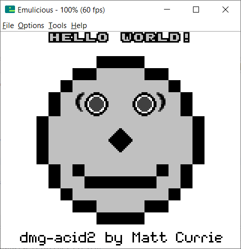
- The `.gb` file is also called "the ROM file".
- You may open it with a GameBoy emulator (Emulicious, BGB, Sameboy,
etc.) to run it on your computer
- 
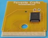
- You may burn an actual ROM chip to create a Gameboy cartridge and
run it on real hardware:
- 
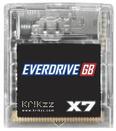
- Or copy the `.gb` file to a microSD card and insert it into an
Everdrive cartridge and run the ROM file on real hardware:
- 
## [5.5]{.header-section-number} What's in a Game ROM {#whats-in-a-game-rom number="5.5"}
- Bytes.
- More precisely:
- instructions
- data: integer values, text, graphics, music, etc.
- In the ROM, instructions and data look the same.
- In the assembly source file, they are defined differently
## [5.6]{.header-section-number} Instructions encoding {#instructions-encoding number="5.6"}
- See the [instruction table](https://gbdev.io/gb-opcodes/optables/)
- The assembler program does the job of converting assembly code into
machine code.
- Top nibble of instruction is given by row, bottom nibble is given by
column.
- For instance `LD C,A` is translated into: `4F`
- Instructions with constant data need the data to be provided as a
second byte.
- For instance `LD C,15` is translated into: `0E 0F`
- For instructions with two bytes constants, the low byte comes firts:
- `JP $AABB` -\> `C3 BB AA`
- `LD HL,$AABB` -\> `21 BB AA`
- The instruction table also provides us the size and number of cycles
(not today's topic) and how it affects flags.
## [5.7]{.header-section-number} Instructions size {#instructions-size number="5.7"}
- Instructions without data: 1 byte = `opcode`. Eg:
- `ld a,b`
- `and l`
- `add hl,de`
- instructions with 1 byte of data (`ld r,n`, `and n`...): 2 bytes =
`opcode data`
- instructions with 2 bytes of data (`ld hl,nn`, `jp nn`, `call nn`...):
3 bytes = `opcode data data`
- Prefixed instructions (second page) are 2 bytes = `CB opcode`
- shift, rotate, swap and bit instructions
## [5.8]{.header-section-number} Defining constant data {#defining-constant-data number="5.8"}
- `DB` defines a sequence of bytes that will be stored in the final
image.
```{.sourceCode
DB 1,2,3,4
- Example:
```{.sourceCode ; assume A contains a value between 0 and 15 ld hl, myarray ld d,0 ld e,a add hl,de ld a,[hl] loop: jp loop
myarray: DB 10, 100, 213, 133, 7, 82, 48, 130, 35, 123, 182, 155, 0, 218, 243, 45
- `DS`: fill a region of memory with some repeated values

```{.sourceCode
; outputs the following 3 bytes: $AA, $AA, $AA
DS 3, $AA
[5.9]{.header-section-number} Exercise 1 {#exercise-1-4 number="5.9"}
What sequence of bytes is produced by the assembler, when taking the following snippet as input? Provide the answer in hexadecimal.
```{.sourceCode xor a DS 2, \(BB ld b,\)00 ld c,$AA DB $AB, $CD inc (hl)
## [5.10]{.header-section-number} The Game Boy Memory Map {#the-game-boy-memory-map number="5.10"}

Range           Size    Description   Access

---

\$0000-\$7FFF   32 KB   Game ROM      Read-only
\$C000-\$DFFF   8 KB    Work RAM      Read-write

- The ROM contains both code and data from our assembly program, then
  the rest of the 32 KBytes is filled with a constant value (usually all
  zeros `$00` or all ones `$FF`).
- Real games can be bigger than 32 KBytes by using a technique called
  "bank switching".
- The Work RAM are 8 KBytes of available space for our game's variables.

## [5.11]{.header-section-number} RGBASM: Sections {#rgbasm-sections number="5.11"}

- An `.asm` file can define multiple sections of code.
- When a section beginning address is provided, the assembler can
  determine the absolute memory addresses of labels inside of it.
- But it is also possible to leave the section "floating" (specify no
  address) so the linker decides where to put it.
- In that case, the `.o` file does not contain addresses to these labels
  of floating sections, instead there are placeholders, and the linker
  will finally decide them. unless explicitely stated.
- Syntax:

```{.sourceCode
SECTION name, type
SECTION name, type[addr]
- Possible
types: ROM0: A ROM section.addrcan range from$0000to$7FFF.WRAM0: The Work RAM, where you can define variables.addrcan range from$C000to$DFFF.
[5.12]{.header-section-number} Exercise 2 {#exercise-2-4 number="5.12"}
2.1 Consider the following snippet:
```{.sourceCode SECTION "Main", ROM0[$1000] main: dec a dec b add b jp main
What is the sequence of bytes produced by the assembler from this
section?

2.2

```{.sourceCode
SECTION "Functions", ROM0[$3000]
parity:
   dec a
   jp z,odd
   dec a
   jp z,even
   jp parity
even:
   ld a,0
   ret
odd:
   ld a,1
   ret
What is the sequence of bytes produced by the assembler from this section?
2.3
```{.sourceCode SECTION "Main", ROM0[$2000] main: ld a,50 ld [health], a ld hl,counter ld [hl],30 loop: dec [hl] push hl ld hl,counter dec [hl] pop hl jp loop
SECTION "Variables", WRAM0[$C000] health: DS 1 counter: DS 1
What is the sequence of bytes produced by the assembler from this
section?

## [5.13]{.header-section-number} Relative jumps {#relative-jumps number="5.13"}
jp nn C3 nn nn jump to nn, PC=nn jp f,nn xx nn nn conditional jump if nz,z,nc,c jr PC+dd 18 dd relative jump to nn (PC=PC+8-bit signed) jr f,PC+dd xx dd conditional relative jump if nz,z,nc,c
- `jr` instructions are smaller than `jp` instructions (2 bytes instead
  of 3 bytes)
- `jr` has a limited range of jumping, appropiate for local loops
- `jr` offset is calculated by the assembler, does not need to be
  resolved by the linker
- base address is the memory address of the next instruction. So a "JR
  00" would just mean do not jump. "JR FE" (-2) is an infinite loop upon
  itself.

## [5.14]{.header-section-number} Exercise 3 {#exercise-3-4 number="5.14"}

3.1

```{.sourceCode
SECTION "Functions", Rom0[$3000]
parity:
   dec a
   jr z,odd
   dec a
   jr z,even
   jr parity
even:
   ld a,0
   ret
odd:
   ld a,1
   ret
What is the machine code produced by the assembler from this section?
3.2 Code golf. Rewrite the previous function into a functionally equal one but with the smallest possible amount of bytes. Show the machine code.
[5.15]{.header-section-number} RGBASM: labels {#rgbasm-labels number="5.15"}
- One of the assembler's main tasks is to keep track of addresses for you, so you can work with meaningful names instead of numbers.
- A label is defined by writing its name at the beginning of a line, followed by one or two colons, without any whitespace between the label name and the colon(s).
- When defining a local label, the colon can be omitted, and
rgbasmwill act as if there was only one. - A label is local if its name contains a dot
‘.’; otherwise, it is said to be global - More than one dot in label names is not allowed.
- For convenience, local labels can use a shorthand syntax: when a symbol name starting with a dot is found (for example, inside an expression, or when declaring a label), then the current "label scope" is implicitly prepended.
- Defining a global label sets it as the current "label scope", until the next global label definition, or the end of the current section.
- Some examples of label definitions:
```{.sourceCode GlobalLabel: AnotherGlobal: .locallabel ; This defines "AnotherGlobal.locallabel" .another_local: AnotherGlobal.with_another_local:
## [5.16]{.header-section-number} Exercise 4 {#exercise-4-4 number="5.16"}

Get the program `checksum.asm` and follow the instructions of the two
questions.

# [6]{.header-section-number} Week 6 {#week-6 number="6"}

## [6.1]{.header-section-number} Topics {#topics-2 number="6.1"}

- Graphic rendering on the Game Boy
- Running the toolchain

## [6.2]{.header-section-number} Program Study: `first.asm` {#program-study-first.asm number="6.2"}

- Download `first.asm` and `hardware.inc` from the Moodle page, folder
  "Lab files".
- To build it, run:

```{.sourceCode
$ rgbasm  first.asm -o first.o
$ rgblink first.o -o first.gb
$ rgbfix  -v -p 0 first.gb
Then open it with an emulator (BGB, Emulicious).
Alternatively, upload first.asm into the online interface
https://gbdev.io/rgbds-live/.
[6.3]{.header-section-number} Beginning of a program {#beginning-of-a-program number="6.3"}
```{.sourceCode INCLUDE "hardware.inc"
SECTION "Header", ROM0[$0100]
jp EntryPoint
ds $150 - @, 0 ; Fill header with zero's until address $014F
; Will be replaced by the header by rgbfix
EntryPoint:
...
- [`INCLUDE "hardware.inc"`](https://raw.githubusercontent.com/gbdev/hardware.inc/refs/heads/master/hardware.inc)[: constants, memory](https://raw.githubusercontent.com/gbdev/hardware.inc/refs/heads/master/hardware.inc)[locations](https://raw.githubusercontent.com/gbdev/hardware.inc/refs/heads/master/hardware.inc)
- Your program really starts at label `EntryPoint`
- Before that:
- `$0000` - `$0100`: internal boot ROM of Gameboy
- `$0103` - `$014F`: ROM header
- `rgbfix` writes the ROM header
## [6.4]{.header-section-number} Hardware of the Game Boy: CPU and PPU {#hardware-of-the-game-boy-cpu-and-ppu number="6.4"}
- CPU and PPU are two circuits in the Gameboy that run in parallel.
- PPU: Picture (or Pixel) Processing Unit
- The picture is displayed on the LCD screen, has a resolution of
160×144 pixels and shows 4 shades of grey.
- PPU draws on the LCD screen at 60 Hz.
- PPU is connected to VRAM (Video RAM, 8 KBytes), and OAM (Object
Attribute Memory, 160 Bytes); but not to the ROM or WRAM.
- CPU is also connected to VRAM and OAM but can only access them when
PPU is not busy with them.
- Finally, CPU is connected to PPU and can control it to some extent.
## [6.5]{.header-section-number} Graphic Elements: Tiles {#graphic-elements-tiles number="6.5"}
- Tiles are the basic ingredient for rendering graphics.
- A tile is a 8x8 matrix of pixels.
- Each pixel corresponds to one of the four colors (shades of grey).
- Tiles are stored at the beginning of the VRAM.
- We refer to each tile by its Tile ID, its position from the beginning
of the VRAM, starting at ID 0.
## [6.6]{.header-section-number} Graphic Elements: Background Layer {#graphic-elements-background-layer number="6.6"}
- The Background layer is a matrix of tile IDs.
- We will come back to the background layer in a few weeks.
## [6.7]{.header-section-number} Graphic Elements: Objects (or Sprites) {#graphic-elements-objects-or-sprites number="6.7"}
- Objects are tiles that can move independently on the screen.
- The maximum number of objects on screen is 40.
- The Object Attribute Memory (OAM) is an array of 40 elements of 4
bytes each:
- Y and X coordinates
- Tile ID
- Attributes (or Flags): palette, flip vertically, flip horizontally,
etc.
## [6.8]{.header-section-number} Constructing the Frame {#constructing-the-frame number="6.8"}
- PPU gets all the useful data from the VRAM and OAM.
- For now, we will concentrate on the object layer only.
## [6.9]{.header-section-number} Memory Map {#memory-map number="6.9"}
Address Size Description Access Constant
---
\$0000-\$7FFF 32 KB Game ROM Read-only
**$****8000-** **$****9FFF** **8 KB** **Video RAM** **Read-write** `_VRAM`
\$C000-\$DFFF 8 KB Work RAM Read-write `_RAM`
**$****FE00-** **$****FE9F** **160 B** **OAM** **Read-write** `_OAMRAM`
**$****FF40** **1 B** **LCD Control Register** **Read-write** `rLCDC`
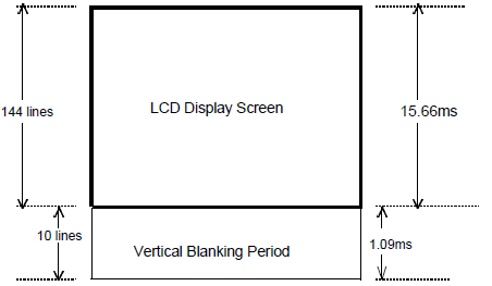
**$****FF44** **1 B** **LCD Y Coordinate Register** **Read-only** `rLY`
- Constants are defined in `hardware.inc`
- `rLY` is read-only:
- Contains the current line being rendered on the LCD by PPU
- Value increments from 0 to 153 and repeats.
- 0-\>143: the current frame is being drawn (144 lines)
- 144-\>153: Vertical Blank (VBlank), a short pause between two frames
- Video RAM and OAM are acessible by the CPU when:
- PPU is turned off (typically at beginning of program)
- during VBlank (typically during normal function of program)
## [6.10]{.header-section-number} Turning off the PPU {#turning-off-the-ppu number="6.10"}
```{.sourceCode
call WaitVBlank
ld a, 0
ld [rLCDC], a
...
WaitVBlank:
ld a, [rLY]
cp 144
jr nz, WaitVBlank
ret
- When PPU is off, CPU has access to VRAM as long as it wishes.
- It is a good moment for initializing Video RAM and the OAM.
[6.11]{.header-section-number} Copying tiles from ROM to Video RAM {#copying-tiles-from-rom-to-video-ram number="6.11"}
```{.sourceCode CopyTileDataToVRAM: ld de, Tiles ld hl, _VRAM ld bc, TilesEnd - Tiles .copy: ld a,[de] inc de ld [hl],a inc hl ld [hl],a inc hl dec bc ld a,b or c jr nz, .copy ret
SECTION "TilesData", ROM0
Tiles: ; Tile ID 0: smiling face DB %01111110 DB %10000001 DB %10100101 DB %10000001 DB %10100101 DB %10011001 DB %10000001 DB %01111110 TilesEnd:
## [6.12]{.header-section-number} Preparing the OAM {#preparing-the-oam number="6.12"}

- Object Attribute Memory (OAM) is an array of 40 elements, each of 4
  bytes:
  - Y position
    - Y = object vertical position on screen + 16
    - Y = 0 or Y \>= 160: completely off-screen
  - X position
    - X = object horizontal position on screen + 8.
    - X = 0 or X \>= 168: completely off-screen
  - Tile ID: choose the actual tile to display
  - Attributes: will leave it 0 for now
- Setting the Y coordinate to 0 hides the object from screen.

```{.sourceCode
ResetOAM:
  ld hl, _OAMRAM
  ld b,40*4
  ld a,0
.loop:
  ld [hl],a
  inc hl
  dec b
  jr nz,.loop
  ret
[6.13]{.header-section-number} Preparing the Object Palette {#preparing-the-object-palette number="6.13"}
```{.sourceCode ld a,%11111100 ; set a black and white palette ld [rOBP0], a
- Palette is a byte that assigns a screen color to each possible tile
  pixel value.
- Any non-zero value is drawn as black.
- Game Boy can display 4 levels of grey but we will stick to black and
  white only.
- Simplifies our graphic data.

## [6.14]{.header-section-number} Turning the PPU on again {#turning-the-ppu-on-again number="6.14"}

```{.sourceCode
  ld a, LCDCF_ON | LCDCF_OBJON
  ld [rLCDC], a
rLCDCis loaded with a byte.- Each bit of that byte has a meaning.
LCDCF_ONturns the PPU onLCDCF_OBJONturns the object layer onLCDCF_BGONturns the background layer on (not used here)
[6.15]{.header-section-number} Putting it together {#putting-it-together number="6.15"}
```{.sourceCode EntryPoint: call WaitVBlank ld a,0 ld [rLCDC],a call CopyTileDataToVRAM call ResetOAM
ld hl,_OAMRAM ; hl points to first object entry ld [hl], 50 ; set Y to 50 inc hl ld [hl], 70 ; set X to 80
ld a,%11111100 ld [rOBP0], a
ld a, LCDCF_ON | LCDCF_OBJON ld [rLCDC], a
MainLoop: jp MainLoop
## [6.16]{.header-section-number} Adding movement ( `move.asm` ) {#adding-movement-move.asm number="6.16"}

- What if we want the object to move between each frame?
- OAM is only accessible by CPU during VBlank.
- So, for instance:

```{.sourceCode
  ...      ; same initialization as before
MainLoop:
  call WaitVBlank
  ld   hl, _OAMRAM
  inc  [hl]         ; increment Y
  inc  hl
  inc  [hl]         ; increment X
  jp   MainLoop
[6.17]{.header-section-number} Exercise {#exercise number="6.17"}
Download the program first.asm and solve the exercises.
[6.18]{.header-section-number} Resources {#resources number="6.18"}
- RGBDS: https://rgbds.gbdev.io
- Install instructions are available on Moodle page.
hardware.inchttps://github.com/gbdev/hardware.inc- Emulators:
- BGB: https://bgb.bircd.org/. Only a Windows executable is provided, so wine is necessary to execute it on Linux or Mac OS.
- Emulicious: https://emulicious.net/
[7]{.header-section-number} Week 7 {#week-7 number="7"}
[7.1]{.header-section-number} Topics {#topics-3 number="7.1"}
- Random Walk
- Use of Shadow OAM
[7.2]{.header-section-number} VBlank {#vblank number="7.2"}
- VBlank lasts 4560 CPU cycles
- The usual organization of a program's main loop is:
- Outside VBlank: Compute the new values of OAM and save them into Work RAM
- In VBlank: Only copy values from Work RAM to OAM
- The hope is that 2. can fit into 4560 cycles; but it is not easy!
[7.3]{.header-section-number} Timing in Assembly {#timing-in-assembly number="7.3"}
- Instruction table shows instruction size (left), but also instruction timing (right).
- Timing is expressed as clock cycles.

Examples:
INC A,DEC A: 4 cyclesLD C,H,LD C,L: 4 cyclesLD A, n8: 8 cyclesLD C, [HL]: 8 cycles- In general:
- Each memory access requires +4 cycles
- Bigger instructions take longer
- Conditional instructions have two timings
- when jump taken: slow
- when jump not taken: fast

[7.4]{.header-section-number} Calculating Timing of Some Code {#calculating-timing-of-some-code number="7.4"}
- Without loops:
- total is the sum of the timing of each instruction
- With loops:
- count how many time the loop body repeats
- in last loop body execution, jump is not taken
- total = (# loop repeats) * (body + jump instruction times) - (difference between jump taken and jump not taken)
[7.5]{.header-section-number} Example 1 {#example-1 number="7.5"}
```{.sourceCode ResetMemory: ; inputs: HL: memory location ; B>0: how many bytes to reset ld a,0 ; 8 .loop: ld [hl],a ; 8 inc hl ; 8 dec b ; 4 jr nz,.loop ; 12/8 ret ; 16
; total = ?
## [7.6]{.header-section-number} Load from/to memory with post-increment {#load-fromto-memory-with-post-increment number="7.6"}
ldi (HL),A (HL)=A, HL=HL+1 ldi A,(HL) A=(HL), HL=HL+1 ldd (HL),A (HL)=A, HL=HL-1 ldd A,(HL) A=(HL), HL=HL-1
Also written as: `ld [hli], a` or `ld [hl+],a`.

Same time as load from/to memory without post-increment: 8 cycles saved.

## [7.7]{.header-section-number} Example: faster {#example-faster number="7.7"}

```{.sourceCode
ResetMemory:
; inputs: HL:  memory location
;         B>0: how many bytes to reset
  ld a,0      ;         8
.loop:
  ld [hl+],a  ;         8
  dec b       ;         4
  jr nz,.loop ;         12/8
  ret         ;         16

; total =   ?
[7.8]{.header-section-number} Program Study: Random Walk ( walk.asm ) {#program-study-random-walk-walk.asm number="7.8"}
Download walk.asm from the Moodle page, folder "Lab files".
Outline of the program:
Initialization:
  1. Wait for VBlank
  2. Turn off PPU
  3. Set objects palette
  4. Copy tile from ROM to VRAM
  5. Reset OAM
  6. Reset ShadowOAM
  7. Initialize random coordinates in ShadowOAM
  8. Turn on PPU (only object layer, no background)

Main loop:
  9.  Update objects coordinates: move 1 step to random direction each
  10. Wait for VBLank
  11. Copy ShadowOAM to OAM
[7.9]{.header-section-number} Code snippet: generating "random" values {#code-snippet-generating-random-values number="7.9"}
- There is no real source of randomness on the GameBoy, but let us try to write a "good enough" function anyway.
- We can attempt to mix register values that may change between
different calls.
xoroperation is a good way to mix values (preserves 50%/50% distribution of 0's and 1's). rDIVis a hardware counter that increments every 256 clock cycles.
```{.sourceCode RandomByte: ld a,[rDIV] xor b xor h xor l xor [hl] ret
## [7.10]{.header-section-number} Shadow OAM {#shadow-oam number="7.10"}

```{.sourceCode
SECTION "Variables", WRAM0
shadowOAM: DS 160 ; same size as OAM
Initialization:
- reset its values
- write in
shadowOAMthe random coordinates of objects
[7.11]{.header-section-number} Copying ShadowOAM to OAM {#copying-shadowoam-to-oam number="7.11"}
This operation must be done in VBlank (4560 cycles).
Time of the following function if OBJCOUNT=40? What is the maximum value
of OBJCOUNT to fit into VBlank time?
```{.sourceCode CopyShadowOAMtoOAM: ld hl, ShadowOAM ; 12 ld de, _OAMRAM ; 12 ld b, OBJCOUNT*4 ; 8 .loop: ld a,[hl] ; 8 ld [de],a ; 8 inc hl ; 8 inc de ; 8 dec b ; 4 jr nz, .loop ; 12/8 ret ; 16
## [7.12]{.header-section-number} Copying ShadowOAM to OAM, faster {#copying-shadowoam-to-oam-faster number="7.12"}

- Use post-increment instruction
  - Save 8 cycles
- `_OAMRAM` fits in the memory page \$FE00, so register `d` will not
  change. Increment e only.
  - Save 4 cycles
- New timing? How many objects can be copied within 4560 cycles?

## [7.13]{.header-section-number} Loop Unrolling {#loop-unrolling number="7.13"}

- 12 cycles are spent by jumping for each loop repeat.
- If we could jump fewer times, we could save cycles.
- Loop unrolling:
  - new body is the old body repeated several times
  - repeating old loop body N times implies jumping N times less

```{.sourceCode
SomeFunction:
  ld b, X              ; 8
.loop:
  [loop body]          ; Y
  jr nz, .loop         ; 12/8
  ret                  ; 16
; 20 + (Y + 12) * X cycles

SomeFunction_Unrolled:
  ld b, X/2            ; 8
.loop:
  [loop body]          ; Y
  [loop body]          ; Y
  jr nz, .loop         ; 12/8
  ret                  ; 16
; 20 + (2*Y + 12) * (X / 2) cycles
; = 20 + (Y + 6) * X cycles
[7.14]{.header-section-number} Copying ShadowOAM to OAM, fast enough {#copying-shadowoam-to-oam-fast-enough number="7.14"}
```{.sourceCode CopyShadowOAMtoOAM: ld hl, ShadowOAM ; 12 ld de, _OAMRAM ; 12 ld b, OBJCOUNT ; 8 .loop: ld a,[hl+] ; 8 ld [de],a ; 8 inc e ; 4 ld a,[hl+] ; 8 ld [de],a ; 8 inc e ; 4 ld a,[hl+] ; 8 ld [de],a ; 8 inc e ; 4 ld a,[hl+] ; 8 ld [de],a ; 8 inc e ; 4 dec b ; 4 jr nz, .loop ; 12/8 ret ; 16
- Repeat loop body 4 times.
- Time spent by all `DEC B + JR` was `OBJCOUNT*4*16 - 4` =
  `OBJCOUNT*64 - 4`
- Now is `OBJCOUNT * 16 - 4`
- New timing:
  - 44 + 24 (for the `CALL`) + 96 \* OBJCOUNT
  - VBlank is 4560 cycles
  - max OBJCOUNT = 46
  - Our target was 40, so updating the OAM will take 3908 cycles with
    652 cycles to spare.

## [7.15]{.header-section-number} Do the random walk {#do-the-random-walk number="7.15"}

```{.sourceCode
UpdateObjects:
  ld hl,ShadowOAM
  ld b, OBJCOUNT
.update:
  push hl
  call RandomByte
  and %00000011
  call z, GoLeft
  cp 1
  call z, GoUp
  cp 2
  call z, GoRight
  cp 3
  call z, GoDown
  pop hl
  inc hl
  inc hl
  inc hl
  inc hl
  dec b
  jr nz, .update
  ret

GoLeft:
  inc hl
  dec [hl]
  ret
GoUp:
  dec [hl]
  ret
GoRight:
  inc hl
  inc [hl]
  ret
GoDown:
  inc [hl]
  ret
[7.16]{.header-section-number} Exercises {#exercises number="7.16"}
- Modify
InitializeObjectsso that their initial coordinates is always within screen bounds. - Modify
UpdateObjectsso that objects would wrap around the screen. - Modify
UpdateObjectsso that only 1 object (randomly selected) moves at each frame.
[8]{.header-section-number} Week 8 {#week-8 number="8"}
[8.1]{.header-section-number} Today's topic {#todays-topic number="8.1"}
- Metaobjects
- Key input
[8.2]{.header-section-number} Metaobjects {#metaobjects number="8.2"}
- Metaobjects offer a way to create larger on-screen entities
- An alternative word for (meta)object is (meta)sprite

[8.3]{.header-section-number} Implementing metaobjects {#implementing-metaobjects number="8.3"}
- Declare array(s) to store the (x,y) coordinates of metaobjects.
- Apply your program's logic to these metaobjects.
- To draw these metaobjects on screen, these (x,y) coordinates must be converted to (x,y) coordinates of (OAM) objects
- A function must be written to convert each metaobject's (x,y) coordinates to several object coordinates in the Shadow OAM.
- In VBlank, copy shadow OAM to OAM as usual.
[8.4]{.header-section-number} Exercise 1: walkmeta.asm {#exercise-1-walkmeta.asm number="8.4"}
- Get the file
walkmeta_TODO.asm - It is another random walk program, but instead of 40 small faces, it should have 10 big faces (16x16 pixels), each doing a random walk.
- This is still 40 objects, but they are organized by groups of 4.

Each big face is made of 4 tiles:
```{.sourceCode ; tile id 1; big smiling face NW corner DB %01111111 DB %10000000 DB %10000000 DB %10011000 DB %10011000 DB %10000000 DB %10000000 DB %10000000 ; tile id 2; big smiling face NE corner DB %11111110 DB %00000001 DB %00000001 DB %00011001 DB %00011001 DB %00000001 DB %00000001 DB %00000001 ; tile id 3; big smiling face SE corner DB %10000000 DB %10000000 DB %10100000 DB %10010000 DB %10001111 DB %10000000 DB %10000000 DB %01111111 ; tile id 4; big smiling face SW corner DB %00000001 DB %00000001 DB %00000101 DB %00001001 DB %11110001 DB %00000001 DB %00000001 DB %11111110
- Key idea: instead of storing and updating each object's coordinates
  separately, treat metaobjects like first-class citizens
- Use an array to store the `(y,x)` coordinates of each metaobject:

```{.sourceCode
DEF METAOBJCOUNT EQU 10

SECTION "Variables", WRAM0
MetaCoord: DS 20
ShadowOAM: DS 160
- Get the
walkMeta_TODO.asmfile - Search each
TODOand complete the missing code. - Deliverable:
walkMeta.asm
[8.5]{.header-section-number} Keys Input {#keys-input number="8.5"}
- The inputs of the Gameboy are:
- the directional pad with 4 directions: up, right, down, left
- 4 more keys: A, B, select, start
- The
P1hardware register is used to know the current state of all keys ld a,[rP1]then reada...- The use of
rP1is actually complex, so we will use a function calledreadKeys.
[8.6]{.header-section-number} Input Function readKeys {#input-function-readkeys number="8.6"}
The definition below can be downloaded from the file readKeys.asm from
the Moodle folder "Lab Files":
```{.sourceCode ;--------------------------------------------------------------------- readKeys: ;--------------------------------------------------------------------- ; Output: ; b : raw state: pressing key triggers given action continuously ; as long as it is pressed ; c : rising edge: pressing key triggers given action only once, ; key must be released and pressed again
; [function implementation omitted]
This function requires two variables: `previous` and `current`, 1 byte
each:

```{.sourceCode
SECTION "Variables", WRAM0
previous: DS 1
current:  DS 1
In the functions's outputs (b,c and current), the bits correspond
to:
- bit 7: down
- bit 6: up
- bit 5: left
- bit 4: right
- bit 3: start
- bit 2: select
- bit 1: B button
- bit 0: A button
- The
currentvariable stores the keys that have been pressed since the last time the functionreadKeyswas called. - If you call
readKeysone time per frame, thencurrentcontains the keys pressed in the current frame (rising edge). - You can use the
bit n, [hl]instruction to test it some button has been pressed, for instance:
```{.sourceCode ld hl, current bit 7, [hl] ; checks for DOWN key pressed call nz,move_down
## [8.7]{.header-section-number} Reading keys without repeats (or holds) {#reading-keys-without-repeats-or-holds number="8.7"}

- `current` contains the keys that have a rising edge since the last
  time `ReadKeys` was called.
- So it makes sense to call `readKeys` once per frame, then update the
  program state accordingly.
  - Eg. If "up" pressed, decrement the player's `Y` coordinate, etc.
- A typical main loop would be:

```{.sourceCode
MainLoop:
  call readKeys
  ; then act accordingly
  call waitVBlank
  call copyShadowOAMtoOAM
  jp MainLoop
[8.8]{.header-section-number} Exercise {#exercise-6 number="8.8"}
Let us use a random walk program (original or metaobjects). The objective of the exercise is to add support for input as follows:
-
First part: * when "A" is pressed, generate new coordinates for all objects * ensure that to reset again, the "A" key must be released and pressed again * make sure to check what actual key of your computer is mapped to the Gameboy's "A" button
-
Second part: * when "B" is pressed, pause the program * pausing means that objects coordinates are no longer updated on each frame
[8.9]{.header-section-number} Deliverables {#deliverables number="8.9"}
walkMeta.asmresetKey.asm
[9]{.header-section-number} Week 9 {#week-9 number="9"}
[9.1]{.header-section-number} Topics {#topics-4 number="9.1"}
- Background layer
[9.2]{.header-section-number} LCDC register (LCD control) {#lcdc-register-lcd-control number="9.2"}
- known as
rLCDCinhardware.inc - Detailed documentation: https://gbdev.io/pandocs/LCDC.html
- Interesting bits of
[rLCDC](for us) - 7: enable display
- 1: enable object (OBJ) layer
- 0: enable background (BG) layer
```{.sourceCode ; LCD on, OBJ on, BG off ld a, LCDCF_ON | LCDCF_OBJON ld [rLCDC], a
; LCD on, OBJ on, BG on
ld a, LCDCF_ON | LCDCF_BGON | LCDCF_OBJON
ld [rLCDC], a
## [9.3]{.header-section-number} Background Layer (BG) {#background-layer-bg number="9.3"}

- The background is composed of a map (or tilemap) of 32 \* 32 tiles.
- A tilemap is a large matrix of tiles.
- A tilemap only contains references to the tiles, not the tiles
  themselves.
- This makes reusing tiles cheap in memory storage.
- Note that you usually need an empty tile; in that case it is tile id
  0.

## [9.4]{.header-section-number} Data Needed to Render a Frame with BG and Objects {#data-needed-to-render-a-frame-with-bg-and-objects number="9.4"}

VRAM has 8 KBytes of memory. It contains:

- tile data, that can be used by objects and by the background layer
- the background layer itself, which is a 32x32 matrix of tile IDs

## [9.5]{.header-section-number} LCDC bit 4 {#lcdc-bit-4 number="9.5"}

What address do the background layer read the tile data:

- LCDC bit 4: BG Tile Data address:
  - If 0 = `8800–97FF`
  - If 1 = `8000–8FFF`: (same range as objects)

The object layer always reads tile data from address `8000` (beginning
of VRAM), it cannot be changed.

For simplicity, we will prefer to always set LCDC bit 4 to 1, so the
tiles of your game are all at the same place (you will not use more than
256 tiles in total).

```{.sourceCode
; LCD on, BG on, BG tiles at $8000, OBJ on
  ld a, LCDCF_ON | LCDCF_BGON | LCDCF_BG8000 | LCDCF_OBJON
  ld [rLCDC], a

[9.6]{.header-section-number} LCDC bit 3 {#lcdc-bit-3 number="9.6"}
- The background is a matrix of 32x32 tile IDs
- The PPU reads from one of two possible memory addresses
- LCDC bit 3:
- If 0:
9800-9BFF(constant_SCRN0) - If 1:
9C00-9FFF(constant_SCRN1) - Change this bit to quickly switch between two backgrounds.
[9.7]{.header-section-number} SCY, SCX and BGP registers {#scy-scx-and-bgp-registers number="9.7"}
- Background is
32*32tiles =256*256pixels, bigger than the screen size. SCYandSCXregisters can be used to specify the origin of the visible 160x144 pixels area.SCYandSCXhold values in range 0-255.- Set them to 0 to show the first corner of the background (20 tiles wide, 18 tiles high)
- Background has a palette too, stored in
[rBGP]


[9.8]{.header-section-number} Exercise: interacting with the background {#exercise-interacting-with-the-background number="9.8"}
Download mouse_TODO.asm from Moodle. The program implements instant
reading of keys to move the cursor in the 4 directions. You need to fill
in the missing code in the TODO comments so that pressing the A key
changes the background tile below the mouse cursos (toggle from empty to
full).
[9.9]{.header-section-number} Hint: Use the Debugger {#hint-use-the-debugger number="9.9"}
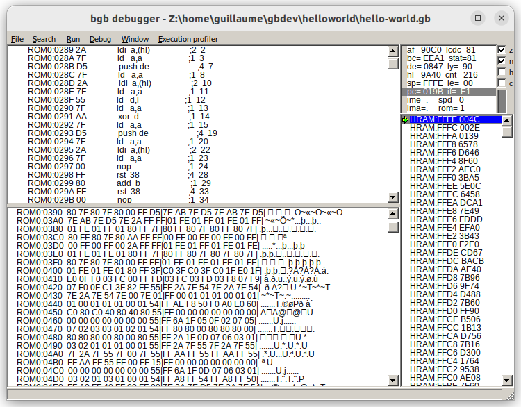
- If the previous exercise requires you to look at what's happening at the register level, you can use the debugger of the emulator; both BGB and Emulicious support step-by-step execution of the CPU.

- When running BGB, hit ESC key.
- Emulation is paused.
- Top right pane:
- CPU registers:
AF,BC,DE,HL,SP,PC - hardware registers:
LY,LCDC - Top left pane: instructions in ROM
- Bottom left pane shows memory as in a hexadecimal viewer
- Bottom right pane shows memory as a sequence of pair of bytes, useful to see stack.
Important BGB Debugger Keys:
- ESC: pause execution and open debugger
- F3: step execution
- F2 or click in margin: set/remove breakpoint
- F9: run (until next breakpoint if there is any)
[9.10]{.header-section-number} Deliverables {#deliverables-1 number="9.10"}
mouse.asm
[10]{.header-section-number} Week 10 {#week-10 number="10"}
[10.1]{.header-section-number} Topics {#topics-5 number="10.1"}
- Jump tables
- State machines
- Text display
- Score display
[10.2]{.header-section-number} Comparing and jumping {#comparing-and-jumping number="10.2"}
Consider the following three snippets:
```{.sourceCode ; Snippet 1 cp 1 jp z, equals1 cp 2 jp z, equals2 cp 3 jp z, equals3 ...
```{.sourceCode
; Snippet 2
    dec a
    jp z, equals1
    dec a
    jp z, equals2
    dec a
    jp z, equals3
    ...
```{.sourceCode ; Snippet 3 dec a ld hl, jumptable ld e, a ld d, 0 add hl, de add hl, de ld a, [hl+] ld h, [hl] ld l, a jp hl
jumptable: dw equals1 dw equals2 dw equals3 ...
1. **Cycle Count Analysis:**  For each snippet, calculate the total
    number of cycles needed to reach the destination label based on the
    value stored in `A`. Express your result as a function of `A`.


2. **Memory Size Analysis:**  For each snippet, calculate the total
    memory size required, expressed as a function of the number of
    destination labels `N`.

In all cases, it is assumed that `A < N`.

## [10.3]{.header-section-number} Jump Table Application: State Machines {#jump-table-application-state-machines number="10.3"}

A state machine is a good way to organize control flow in assembly
language, especially for managing different screens/levels like title
screens, menus, gameplay levels, end screens, etc.

A state machine breaks your game into distinct "states" where:

- Each state represents a different game mode/screen (title, level 1,
  level 2, end screen)
- The game is only in one state at a time
- The transisions between states are clear and are based on conditions

The implementation requires state handlers, each state handler is a
function that:

- Handles state-specific logic
- Checks for transition conditions
- Updates the state variable when needed

The conversion from state (a variable's value) to executing a state
handler (a function) can be implemented with a jump table.

Example:

```{.sourceCode
    ; some event just updated [state]
    ...
    ld a, [state]       ; Load the current game state
    ld hl, state_table  ; Load the address of the jump table
    ld e, a             ; Use state as the index
    ld d, 0
    add hl, de          ; Add the index to HL
    add hl, de          ; Multiply index by 2 (2 bytes per address)
    ld a, [hl+]         ; Load low byte of the address
    ld h, [hl]          ; Load high byte of the address
    ld l, a             ; Complete the full address
    jp hl               ; Jump to the state's handler

state_table:
    dw title_screen     ; State 0
    dw main_game        ; State 1
    dw pause_menu       ; State 2
    ...

title_screen:
    ; Code for title screen
    jp title_loop

main_game:
    ; Code for main game
    jp main_loop

pause_menu:
    ; Code for pause menu
    jp pause_loop
The main benefit is organization and maintainability. In particular, it makes it easier to add or remove states as game evolves.
[10.4]{.header-section-number} Real-world example: Tetris {#real-world-example-tetris number="10.4"}
The disassembled and commented code can be found at https://github.com/alexsteb/tetris_disassembly. A few explanations:
- variable
rGAME\_STATUS holds the current state of the game (titlescreen, in-game, game lost animation,etc.) - code at ROM address $28 does the jumptable
(it is called by the
rst $28instruction, a smallercall) - function
State\_Machine does the game-status-to-function dispatch,using the previous piece ofcode
[10.5]{.header-section-number} Exercise smoothWalk.asm {#exercise-smoothwalk.asm number="10.5"}
This time we want to showcase a simple state machine, not about a program's state but about an entity's state. Actually, several entities' states!
Download smoothWalk_TODO.asm, a well-known randomWalk.asm program
with a reset key if you press A. You can also run the .gb file to see
the desired behaviour.
- Each object can be in 5 states:
```{.sourceCode DEF IDLE EQU 0 DEF UP EQU 1 DEF RIGHT EQU 2 DEF DOWN EQU 3 DEF LEFT EQU 4
- `IDLE` is the only non-moping state; when moving, an object has as
  certain amount of steps to go in the same direction until coming back
  to `IDLE` state.
- The coordinates and the states of each object are stored in the
  following array that can accomodate up to 40 objects:

```{.sourceCode
Coordinates: DS 80 ; (y,x)
States: DS 80 ; (DIRECTION, COUNTER)
- The
UpdateObjectsfunction must fulfill the following description:
```{.sourceCode UpdateObjects: ; when idle: ; * 1/16 probability: choose direction (among 4), choose counter (4..16) ; * otherwise stay idle ; when non idle: ; * move object along chose direction, decrement counter ; * if counter == 0, set object to idle
- Main loop structure:

```{.sourceCode
MainLoop:
  call readKeys
  call MaybeReset
  call UpdateObjects    ; modify the arrays Coordinates and States only
  call UpdateShadowOAM
  call WaitVBlank
  call CopyShadowOAMtoOAM
  jp MainLoop
Fill in the missing implementation of UpdateObjects.
[10.6]{.header-section-number} Strings in Tetris' VRAM {#strings-in-tetris-vram number="10.6"}


[10.7]{.header-section-number} Strings in RGBASM {#strings-in-rgbasm number="10.7"}
```{.sourceCode DB "Hello, world!"
- a *charmap* (or character map) is a mapping from characters to bytes
- The "character constant" form yields the value the character maps to
  in the current charmap.
- By default, the ASCII code is used (eg, `"A"` yields 65)

## [10.8]{.header-section-number} Character Maps {#character-maps number="10.8"}

- When writing text strings, the character encoding in the ROM may need
  to be different than the source file encoding
  - Eg Tetris uses another encoding
- For example, uppercase letters may be placed starting at tile index
  128, which differs from ASCII starting at 65.

Character maps allow mapping strings to arbitrary 8-bit values:

```{.sourceCode
CHARMAP "A", 1
CHARMAP "B", 2
CHARMAP "C", 3
CHARMAP "<heart>", 4
CHARMAP " ", 5
- This would result in
DB "ABC ABC<heart>" being equivalent toDB 1,2,3,5,1,2,3,4`. - One
CHARMAPcommand is needed for each character. - Eg: https://github.com/pret/pokered/blob/master/constants/charmap.asm#L201
[10.9]{.header-section-number} Zero-terminated strings {#zero-terminated-strings number="10.9"}
- If you adopt the convention that strings ends with a 0, then a function to copy the string to the background map can work as follow:
```{.sourceCode DisplayText: ; inputs: ; HL: zero-terminated string ; DE: destination address (in the background) .loop: ld a, [hl+] ; Load character from the string or a ret z ; Stop when encountering zero ld [de], a inc de jr .loop ret
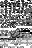
## [10.10]{.header-section-number} Example from Tetris ROM {#example-from-tetris-rom number="10.10"}

The tiles:

```{.sourceCode
characters:
 DB $00,$3C,$66,$66,$66,$66,$3C,$00 ; 0
 DB $00,$18,$38,$18,$18,$18,$3C,$00 ; 1
 DB $00,$3C,$4E,$0E,$3C,$70,$7E,$00
 DB $00,$7C,$0E,$3C,$0E,$0E,$7C,$00
 DB $00,$3C,$6C,$4C,$4E,$7E,$0C,$00
 DB $00,$7C,$60,$7C,$0E,$4E,$3C,$00
 DB $00,$3C,$60,$7C,$66,$66,$3C,$00
 DB $00,$7E,$06,$0C,$18,$38,$38,$00
 DB $00,$3C,$4E,$3C,$4E,$4E,$3C,$00 ; 8
 DB $00,$3C,$4E,$4E,$3E,$0E,$3C,$00 ; 9
 DB $00,$3C,$4E,$4E,$7E,$4E,$4E,$00 ; A
 DB $00,$7C,$66,$7C,$66,$66,$7C,$00 ; B
 DB $00,$3C,$66,$60,$60,$66,$3C,$00 ; C
 DB $00,$7C,$4E,$4E,$4E,$4E,$7C,$00
 DB,$00,$7E,$60,$7C,$60,$60,$7E,$00
 DB $00,$7E,$60,$60,$7C,$60,$60,$00
 DB $00,$3C,$66,$60,$6E,$66,$3E,$00
 DB $00,$46,$46,$7E,$46,$46,$46,$00
 DB $00,$3C,$18,$18,$18,$18,$3C,$00
 DB $00,$1E,$0C,$0C,$6C,$6C,$38,$00
 DB $00,$66,$6C,$78,$78,$6C,$66,$00
 DB $00,$60,$60,$60,$60,$60,$7E,$00
 DB $00,$46,$6E,$7E,$56,$46,$46,$00
 DB $00,$46,$66,$76,$5E,$4E,$46,$00
 DB $00,$3C,$66,$66,$66,$66,$3C,$00
 DB $00,$7C,$66,$66,$7C,$60,$60,$00
 DB $00,$3C,$62,$62,$6A,$64,$3A,$00
 DB $00,$7C,$66,$66,$7C,$68,$66,$00
 DB $00,$3C,$60,$3C,$0E,$4E,$3C,$00
 DB $00,$7E,$18,$18,$18,$18,$18,$00
 DB $00,$46,$46,$46,$46,$4E,$3C,$00
 DB $00,$46,$46,$46,$46,$2C,$18,$00
 DB $00,$46,$46,$56,$7E,$6E,$46,$00
 DB $00,$46,$2C,$18,$38,$64,$42,$00  ; X
 DB $00,$66,$66,$3C,$18,$18,$18,$00  ; Y
 DB $00,$7E,$0E,$1C,$38,$70,$7E,$00  ; Z
 DB $00,$00,$00,$00,$00,$60,$60,$00  ; .
 DB $00,$00,$00,$3C,$3C,$00,$00,$00  ; -
characters_end:
```{.sourceCode COPY_CHARACTERS: ld hl, characters ; address of (black-white) character set in ROM ld bc, characters_end-characters ; length of data set ld de, $8000 ; Starting address of tile data in VRAM .loop: ldi a, [hl] ld [de], a inc de ; copy each byte twice into $8000 ld [de], a ; because characters are stored as only black and white inc de ; but the GB uses two bytes per character to allow for 4 colors dec bc ld a, b or c jr nz, .loop ret
- Source: [https://github.com/alexsteb/tetris_disassembly](https://github.com/alexsteb/tetris_disassembly)
- Tetris does not use any string printing function, it just has
pre-loaded background maps.
- More text-intensive games have string printing functions.
## [10.11]{.header-section-number} Exercise {#exercise-7 number="10.11"}
Get the `displayCounter.asm` file from "Lab Files" on Moodle.
The functions to complete are:
- `HandleInput`
- `binToDec`
- `copyDigitsRev`
**Objective:** Create an interactive program that displays a counter
value on the background map. The counter can be incremented,
decremented, or modified using specific keys.
**Requirements:**
1. **Counter Variable:**
- Declare a 1-byte variable, `counter`, initialized to zero.
- The value of `counter` must always be displayed using **3 digits**
(e.g., `005`, `123`), including leading zeros.
2. **Input Handling:**
- `UP`: Increment `counter` by 1, saturating at 255.
- `DOWN`: Decrement `counter` by 1, saturating at 0.
- `RIGHT`: Add 10 to `counter`, saturating at 255.
- `LEFT`: Subtract 10 from `counter`, saturating at 0.
3. **Background Map:**
- Display the 3-digit `counter` value as tiles on the background
map.
- Each digit corresponds to a specific tile ID (e.g., `0` maps to
tile `0`, `1` maps to tile `1`, and so on).
**Functions to Implement:**
1. **`binToDec`**:
- **Input:**
- `A`: some value from 0 to 255
- `HL`: memory address where 3 bytes are available for output
- **Output:**
- Writes the decimal digits of `A` in reverse order at `HL`
- Example: `A = 123` , memory at `HL` stores `3, 2, 1`.
- **Details:**
- Use a naive division-by-10 routine.
2. **`copyDigitsRev`**:
- **Input:**
- `HL`: source buffer (3 bytes in reverse order from `binToDec`)
- `DE`: end of destination buffer (3 bytes in the background map)
- **Output:**
- Copies the digits from the source buffer to the destination
buffer in the correct order (most significant to least
significant digit).
3. **Input Handling Loop:**
- Continuously check for button presses to modify `counter`
accordingly.
Use the Tetris tiles for digits to implement the program.
## [10.12]{.header-section-number} Deliverable {#deliverable number="10.12"}
- `displayCounter.asm`
# [11]{.header-section-number} Week 11 {#week-11 number="11"}
## [11.1]{.header-section-number} Topics {#topics-6 number="11.1"}
- Lookup tables
- Debugger
- Build script and Make
- Diff viewers
## [11.2]{.header-section-number} Lookup table exercise {#lookup-table-exercise number="11.2"}
The objective is to reproduce the following program:
[Video](circle.webm)
This program shows a single object moving into a circle trajectory.
The object's state is represented by an angle, stored as a single byte
variable, whose range is 0 to 255.
Its `(y,x)` coordinates calculated from its angle, thanks to two lookup
tables `yLUT` and `xLUT`.
These lookup tables are generated by a separate C program that uses the
standard `sin` and `cos` functions from `math.h`.
Task:
1. On Moodle, the program `genLut.c` is provided for you to complete.
This program must be completed and run by you to generate a file
`tables.inc`, used by `circlePause.asm`.
2. In the program `circlePause.asm`, only modify the functions that
contain a `TODO` comment (once the functions are implemented you cam
remove the `TODO` line).
3. If time allows, implement a pause feature. By default, the object
moves. When the user presses the A key, the program goes in pause
mode, in which the movement stops. Pressing A key several times
toggles between pause mode and normal mode.
## [11.3]{.header-section-number} Deliverables {#deliverables-2 number="11.3"}
- `circlePause.asm`
- `genLut.c`
## [11.4]{.header-section-number} BGB Debugger {#bgb-debugger number="11.4"}
- When running BGB, hit ESC key.
- Emulation is paused.
- Top right pane:
- CPU registers: `AF`, `BC`, `DE`, `HL`, `SP`, `PC`
- hardware registers: `LY`, `LCDC`
- Top left pane: instructions in ROM
- Bottom left pane shows memory as in a hexadecimal viewer
- Bottom right pane shows memory as a sequence of pair of bytes, useful
to see stack.
## [11.5]{.header-section-number} BGB Debugger Keys {#bgb-debugger-keys number="11.5"}
- ESC: pause execution and open debugger
- F3: step execution
- F2 or click in margin: set/remove breakpoint
- F9: run (until next breakpoint if there is any)
## [11.6]{.header-section-number} Make {#make number="11.6"}
- GNU Make.
- a command that builds executable programs from source code by
following the rules defined in a file called *Makefile*
- Not installed by default. `sudo apt install make`
```{.sourceCode
$ make
- can run specific tasks if they are defined in a file called Makefile inside of the current directory
```{.sourceCode $ make clean $ make dist $ make pdf
## [11.7]{.header-section-number} Makefile basics {#makefile-basics number="11.7"}

General format of *Makefile*:

```{.sourceCode
rule1:
    command_of_rule_1

rule2:
    command_of_rule_2

rule3:
    command_of_rule_3

...
- Lines that contain commands must start with a TAB character.
- The first rule is default when executing
make
[11.8]{.header-section-number} Makefile basics {#makefile-basics-1 number="11.8"}
Usual rules:
-
build project
-
clean
-
build documentation
-
build .zip file distribution archive
[11.9]{.header-section-number} Build project rule {#build-project-rule number="11.9"}
Take it from the run.sh script.
A rule can be multiline, so a sequence of commands.
```{.sourceCode build: rgbasm... rgblink... rgbfix...
## [11.10]{.header-section-number} Clean rule {#clean-rule number="11.10"}

Should delete the binary files generated:

- `*.gb`
- `*.o`
- etc.

```{.sourceCode
clean:
    rm *.o *.gb
[11.11]{.header-section-number} Dist rule {#dist-rule number="11.11"}
Only include source files and documentation in .zip
For instance:
```{.sourceCode dist: zip -r project.zip *.asm Readme.md Makefile
## [11.12]{.header-section-number} Source code management {#source-code-management number="11.12"}

- "My project worked yesterday, today no, what happened?"
- A common issue in software development.
- It is necessary to keep track of the changes in your project.
- This enables you to find and fix errors, and try some changes that may
  not stay in the final version of your project.
- Basic tool for that:
  - use of the `cp` and `mv` commands
  - use of some diff viewer:
    - commandline: `diff`, `colordiff`
    - graphical: `meld`

## [11.13]{.header-section-number} `diff` {#diff number="11.13"}

- the most basic commandline tool for diff viewing
- compare files lines by line
- use `-u` flag for a nice output

```{.sourceCode
$ diff -u file1 file2
- output is a set of line deletes and line inserts to go from
file1tofile2 diff --colororcolordiffto have color output
[11.14]{.header-section-number} What is Meld? {#what-is-meld number="11.14"}
- It's a free, visual diff (difference) and merge tool.
- It helps you easily see the changes between two or three versions of files or folders.
- It's often used with version control systems, but it's also handy for everyday file comparisons.
[11.15]{.header-section-number} Installing Meld {#installing-meld number="11.15"}
- Linux: Use your package manager (e.g.,
sudo apt install meldon Ubuntu). - macOS: Use Homebrew (
brew install meld). - Windows: Download the installer from the Meld website.
[11.16]{.header-section-number} Opening Meld {#opening-meld number="11.16"}
- Menu: Find Meld in your applications menu.
- Terminal: Type
meldfollowed by the files or folders you want to compare (e.g.,meld file1.asm file2.asm).
[11.17]{.header-section-number} Basic Interface {#basic-interface number="11.17"}

- Panes: Meld displays files side-by-side for comparison.
- Highlighting: Differences are highlighted with colors:
- Green: Lines added in the right file.
- Blue: Lines added in the left file.
- Yellow: Lines modified in both files.
- Scrollbars: Scroll both panes together for easy navigation.
[11.18]{.header-section-number} Additional Features {#additional-features number="11.18"}
- Three-way comparison: Compare three files simultaneously for advanced merging.
- File editing: Edit files directly within Meld and see changes reflected in real-time.
[11.19]{.header-section-number} Key Points of Meld {#key-points-of-meld number="11.19"}
- Meld is a valuable tool for understanding file differences.
- Its visual interface makes it easy to grasp changes quickly.
- It's a helpful tool for learning about file management and comparison techniques.
[11.20]{.header-section-number} Other useful commands {#other-useful-commands number="11.20"}
{.sourceCode
$ cp -r src/ src.22.12.08/   # copy complete directory
$ grep .loop main.asm        # seach ".loop" string in file main.asm
$ grep -r .loop src/         # seach ".loop" string in src/ directory
$ grep -ir .loop src/        # -i flag to ignore case
In the vi text editor, use the * key to jump to the next occurence
of the word under cursor.